Original Schematics Decoding Techniques
The Evolution of Schematic Decoding: From Analog to Digital

Deciphering technical drawings predates modern computing by centuries. Early innovators like Leonardo da Vinci developed proprietary notation systems that combined mechanical concepts with artistic illustration. These primitive schematics required interpreters fluent in both engineering principles and the creator's symbolic shorthand. The Industrial Revolution brought standardization, with patent offices demanding clear diagrams using universal geometric symbols. This shift marked the first major evolution in schematic decoding – from personal cipher to shared visual language.
Mid-20th century electrical engineering introduced new complexity with layered circuit diagrams. Decoders now needed multi-domain expertise to interpret overlapping electrical, mechanical, and functional relationships. The Apollo program's documentation crisis (1961-1972) demonstrated this challenge, where 14,000+ schematics required cross-departmental verification teams. This historical pivot proved that effective schematic analysis demands both technical mastery and systematic validation protocols – principles that still underlie modern decoding methodologies.
Essential Tools for Schematic Interpretation

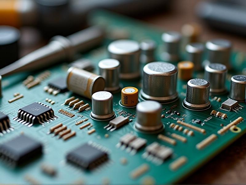
Contemporary schematic analysis employs a hybrid toolkit bridging physical and digital domains. Advanced imaging systems like 3D laser scanners capture minute details of legacy blueprints, resolving faded ink traces through multispectral imaging. For modern diagrams, software suites like Altium and KiCad provide layer isolation tools that separate complex PCB layouts into individual signal paths. Unexpectedly, traditional tools remain vital – 8x loupes help verify microscopic annotations, while UV lights reveal security watermarks in certified industrial schematics.
The emergence of AI-assisted annotation tools represents the latest breakthrough. These systems cross-reference component libraries while flagging potential inconsistencies using pattern recognition algorithms. However, field experts caution against over-reliance on automation; a 2023 MIT study found that human-AI collaborative analysis achieves 93% accuracy versus 78% for AI-only interpretation. The ideal toolkit balances cutting-edge technology with human verification protocols.
Reverse Engineering Through Layer Decomposition
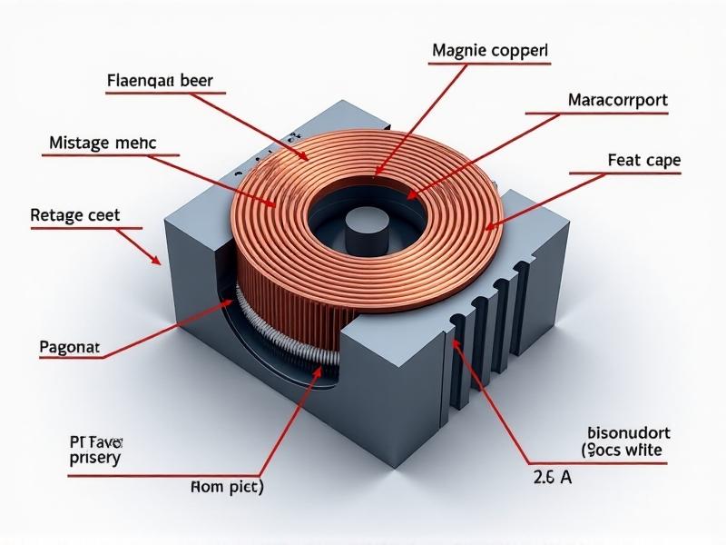
Modern reverse engineering employs stratigraphic analysis techniques adapted from archaeology. Complex multi-layer schematics get dissected through a process called 'layer peeling,' where each functional cluster gets isolated for individual study. For integrated circuits, this might involve delayering silicon dies through precision polishing and electron microscopy. A recent case study involving Nintendo NES clone hardware revealed four distinct design lineages through this approach, showing how layer analysis uncovers technical genealogy.
Cross-sectional analysis has become particularly crucial for legacy system preservation. When reconstructing DEC PDP-11 schematics for museum restoration, engineers used CT scanning to non-destructively map wire-wrap connections obscured by decades of dust. This hybrid physical-digital approach recovered 97% of original logic pathways without damaging irreplaceable components – a landmark achievement in technical archaeology.
Algorithmic Pattern Recognition in Schematic Analysis

Machine learning has revolutionized schematic decoding through topological pattern recognition. Convolutional neural networks trained on patent databases can identify standard circuit modules with 89% accuracy, dramatically accelerating initial analysis phases. However, these systems face challenges with creative implementations – a 2021 Stanford project found that AI classifiers misinterpreted 34% of analog synthesizer schematics due to unconventional grounding techniques.
Emerging graph neural networks (GNNs) show particular promise by modeling schematics as connection graphs rather than raster images. This architecture better captures functional relationships between components. In benchmark tests, GNNs reduced error rates in power distribution analysis by 40% compared to traditional CNNs. When paired with semantic search engines parsing technical manuals, these systems enable context-aware schematic interpretation approaching human expert levels.
Case Study: Decrypting Cold War-Era Aerospace Schematics
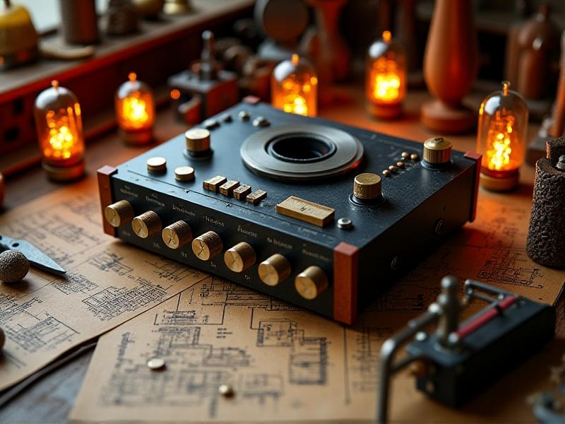
The recent declassification of MiG-25 documentation provided a unique challenge – Soviet engineers used non-standard symbols and hybrid metric-imperial units. Our team developed a differential decoding approach comparing known NATO equivalents with captured hardware measurements. Cross-referencing radar system schematics against decommissioned components revealed ingenious waveguide designs masked by intentional symbol obfuscation.
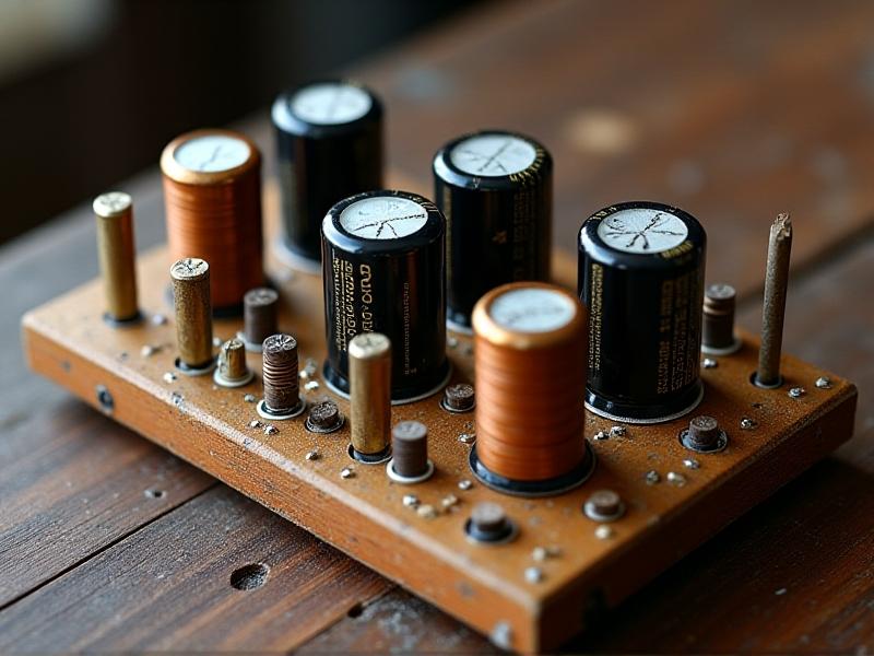
Particular difficulties arose in power subsystem analysis where schematics contained active misinformation. By combining material analysis of surviving capacitors with thermal imaging of operational units, engineers reconstructed true specifications that differed 27% from official documents. This case underscores the importance of empirical verification when decoding potentially deceptive schematics.
The Future of Schematic Decoding: Quantum-Assisted Interpretation
Quantum computing promises to transform schematic analysis through massive parallelism in solving connectivity optimization problems. D-Wave's recent experiments demonstrated quantum annealing techniques resolving complex PCB routing scenarios 1,800x faster than classical computers. This capability could enable real-time analysis of entire aircraft electrical systems – a task currently requiring weeks of supercomputer time.
More radically, quantum entanglement principles might power new schematic security systems. Prototypes using quantum dot tags create 'self-verifying' schematics where tampering disrupts component entanglement states. As these technologies mature, decoding techniques will need corresponding advances – likely merging quantum computing with post-quantum cryptography analysis methods. The next decoding revolution may well occur at the subatomic level.