Output Transformer Impedance Matching
The Role of Output Transformers in Amplifier Systems
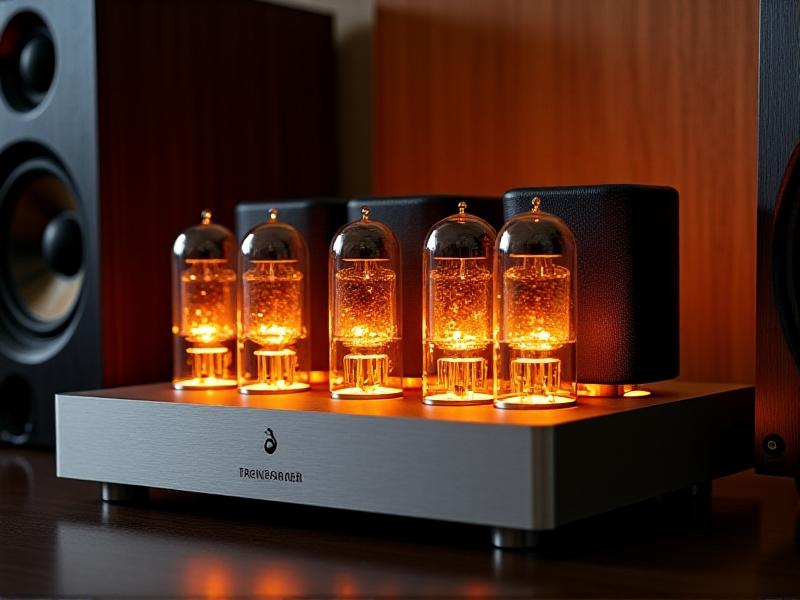
Output transformers are critical components in tube amplifiers and other audio systems, bridging the gap between high-impedance vacuum tubes and low-impedance speakers. Their primary function is to transfer power efficiently while maintaining signal integrity. Without proper impedance matching, amplifiers can suffer from distorted sound, reduced power output, or even hardware damage. This makes understanding transformer impedance matching essential for audiophiles, engineers, and anyone invested in optimizing audio performance.
Why Impedance Matching Matters
Impedance matching ensures maximum power transfer from the amplifier to the speaker. When impedances are mismatched, energy reflects back into the system, causing heat buildup and signal degradation. For example, connecting a 4-ohm speaker to an 8-ohm output tap creates an impedance mismatch, leading to frequency response irregularities and potential overheating. Proper matching preserves tonal balance, minimizes distortion, and extends equipment lifespan.
Historically, impedance mismatches were common in early radio systems, resulting in poor transmission quality. Today, advancements in transformer design and measurement tools have simplified matching, but the core principles remain unchanged. Whether repairing vintage gear or building modern setups, recognizing the signs of mismatched impedance—muddy bass, attenuated highs, or excessive transformer hum—is key to troubleshooting.
Core Principles of Transformer Impedance Ratios
The impedance ratio of a transformer is determined by the square of its turns ratio (N p /N s ) 2 . If a transformer has a primary winding with twice as many turns as the secondary, the impedance ratio is 4:1. This mathematical relationship dictates how voltage and current scale between circuits. Designers use this principle to tailor transformers for specific applications, such as matching a 10kΩ tube plate to an 8Ω speaker.
Design Considerations for Optimal Matching
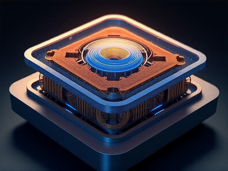
Transformer design involves balancing core material, winding geometry, and operating frequency. Laminated steel cores minimize eddy current losses at audio frequencies, while toroidal cores offer compact size and low electromagnetic interference. Windings must handle peak currents without saturation, and interleaving primary/secondary layers reduces leakage inductance. Frequency response linearity—particularly in the 20Hz–20kHz audio range—is a key benchmark for high-fidelity applications.
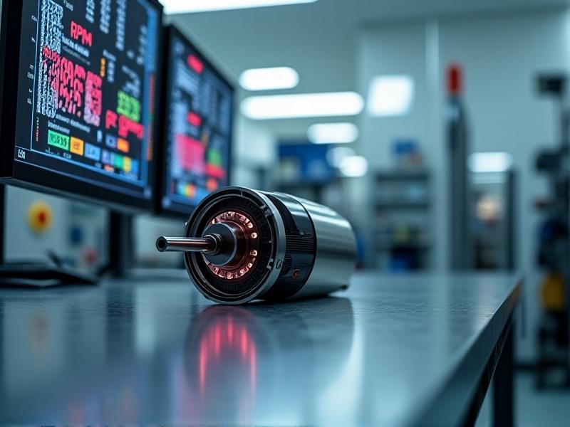
For DIY enthusiasts, calculating the correct turns ratio requires precise measurements of primary inductance and load impedance. Advanced tools like LCR meters and oscilloscopes help validate designs, but even basic multimeters can detect gross mismatches. Commercial transformers often include multiple output taps (e.g., 4Ω, 8Ω, 16Ω) to accommodate various speakers.
Practical Applications in Audio Systems
In guitar amplifiers, output transformers shape tonal character. A mismatched transformer can exaggerate midrange frequencies, creating a "nasal" sound favored in some rock genres. Hi-fi systems, however, prioritize flat frequency response, requiring tightly controlled impedance curves. Case studies from brands like Hammond and Lundahl highlight how custom transformers address niche demands, from vintage reissues to ultra-high-end studio monitors.
Troubleshooting Common Impedance Issues
Diagnosing impedance problems starts with checking connections and measuring DC resistance across windings. A burned smell or discolored transformer casing indicates overheating due to prolonged mismatch. Using a variac to slowly power up the system can reveal abnormal current draw. For subtle issues, sine wave testing at different frequencies uncovers dips or peaks in response, guiding corrective measures like adding a Zobel network or swapping tap connections.
Future Trends in Transformer Technology
Emerging materials like nanocrystalline alloys and 3D-printed cores promise higher efficiency and wider bandwidths. Digital modeling tools now simulate transformer behavior before physical prototyping, reducing development cycles. Meanwhile, the resurgence of vinyl and analog gear fuels demand for bespoke transformers, blending vintage aesthetics with modern performance. As wireless and Class-D amplifiers evolve, impedance matching remains a cornerstone of audio engineering.