Vacuum Tube Biasing Step-by-Step
Understanding Vacuum Tube Biasing: The Heart of Tube Amplification
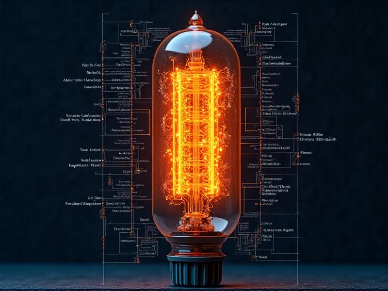
Vacuum tube biasing is the backbone of tube amplifier performance, shaping everything from tonal quality to component longevity. Unlike solid-state circuits, tubes require precise voltage adjustments to operate optimally. Biasing sets the tube’s idle current—the silent, steady flow of electrons when no audio signal is present. Too little current, and the sound becomes thin and distorted; too much, and the tube overheats, risking failure. Mastering this balance unlocks the warm, dynamic sound that audiophiles and musicians cherish. This guide demystifies the process, blending technical precision with practical steps to help you navigate biasing with confidence.
Fixed Bias vs. Cathode Bias: Choosing the Right Approach
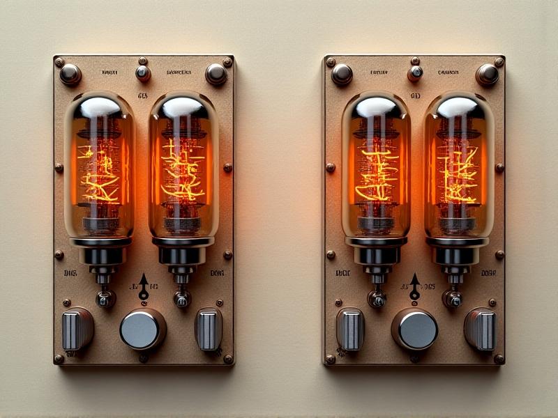
Two primary biasing methods dominate tube amplification: fixed and cathode bias. Fixed bias applies a steady negative voltage to the tube’s control grid, often adjusted via a potentiometer. This method offers fine-tuned control and efficiency, commonly found in high-power amplifiers. Cathode bias, meanwhile, uses a resistor between the cathode and ground, creating self-regulating current flow. While simpler and more forgiving, it sacrifices headroom and power. Guitarists might prefer cathode bias for its natural compression, while hi-fi enthusiasts often lean toward fixed bias for clarity. Understanding these trade-offs is crucial for tailoring your amplifier’s behavior.
Essential Tools for Accurate Tube Biasing
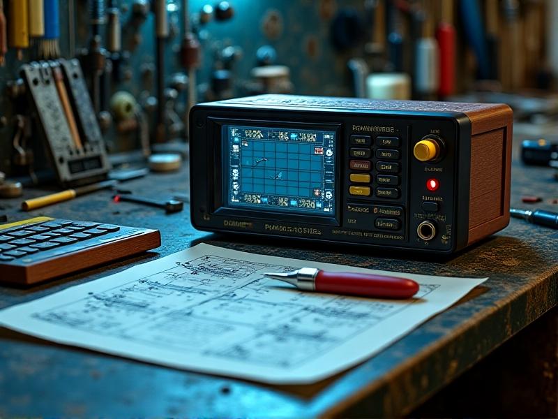
Proper biasing demands specialized tools. A digital multimeter with milliampere measurement is non-negotiable, allowing precise plate current readings. High-voltage probes and insulated screwdrivers ensure safety when working with live circuits. For fixed bias systems, a bias probe kit simplifies measurements by interfacing directly with tube sockets. Don’t overlook a reliable bias calculator—either digital or a trusted chart—to translate voltage readings into optimal settings. A well-lit workspace with anti-static mats and tube socket grippers rounds out the toolkit, creating an environment where precision thrives.
Step 1: Preparing Your Amplifier for Biasing
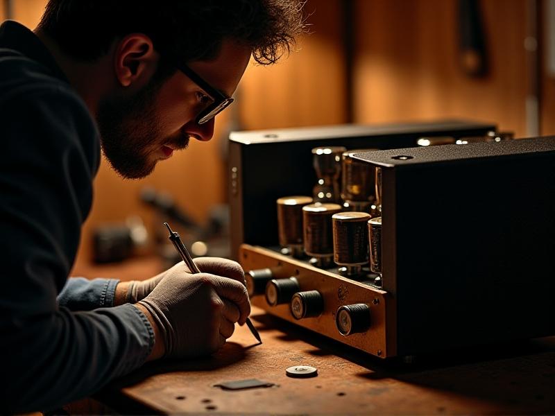
Safety first—disconnect the amplifier from power and discharge capacitors using a grounding probe. Remove the chassis carefully, noting screw placements. Identify the bias test points (often labeled on the circuit board) or tube sockets for probe insertion. For cathode-biased amps, locate the cathode resistor. Let the amplifier sit for 30 minutes to ensure capacitors are fully discharged. Document the original bias settings as a reference point. This preparation minimizes risk and provides a clear roadmap for adjustments, turning a potentially daunting task into a methodical process.
Step 2: Measuring Initial Plate Current
Power up the amplifier using an isolation transformer if available. Set your multimeter to DC milliamps and connect it to the bias test point or tube socket via a bias probe. Let the tubes warm up for 2-3 minutes—cold readings are unreliable. Record the initial plate current, comparing it to the manufacturer’s specifications (typically 60-70% of max dissipation for Class AB). For cathode-biased amps, measure voltage across the cathode resistor and use Ohm’s Law (I = V/R) to calculate current. This baseline measurement determines how far you’ll need to adjust.
Step 3: Adjusting Bias Voltage for Optimal Performance
For fixed bias amps, locate the bias potentiometer—often a small trimmer marked “Bias Adj.” Using an insulated screwdriver, turn it incrementally (1/8th rotations) while monitoring plate current. Aim for ±5% of your target value. In cathode-biased systems, replace the cathode resistor with a higher/lower value to adjust current flow. Allow 10 minutes between adjustments for thermal stabilization. Periodically check multiple tubes in push-pull configurations for balance. The goal isn’t just hitting a number—it’s achieving even current distribution and listening for tonal coherence as you play test tones.
Troubleshooting Common Biasing Issues
Red-plating tubes? Immediate shutdown is crucial—it signals dangerous overcurrent. Check for failing capacitors or incorrect bias supply voltage. If one tube in a matched pair drifts, aging components may be the culprit. Hum or oscillation post-adjustment suggests ground loop issues or poor lead dress. For stubborn amps that won’t hold bias, inspect the bias supply filter caps and diode rectifiers. Remember: Biasing isn’t a set-and-forget process—ambient temperature changes and tube aging require periodic rechecks, especially in touring rigs.
Fine-Tuning Bias for Different Music Genres
Biasing isn’t purely technical—it’s tonal alchemy. Jazz players might underbias (60% dissipation) for smoother compression and earlier breakup. Metal guitarists often push to 70% for tighter bass response. Hi-fi systems thrive at 50-60% for linearity. Experimentation is key: Use a spectrum analyzer to visualize harmonic changes as you adjust. Record identical riffs at various bias points—you’ll hear how higher currents accentuate even-order harmonics (warmth), while lower currents emphasize odd-order harmonics (edge). This is where engineering meets artistry.
Maintaining Your Biased Tubes: Longevity Tips
Properly biased tubes can last thousands of hours. Use a variac to slowly ramp up voltage after long storage periods. Install tube coolers or fans in cramped cabinets. Every 50 playing hours, recheck bias settings—tubes naturally lose emission over time. Store spares in anti-static foam, labeled with their ideal bias voltage. For vintage tubes, reduce bias current by 10-15% to account for decades of use. These practices transform biasing from a chore into a ritual of preservation, ensuring your amp’s voice matures like a fine instrument.